Description
Technical Specification
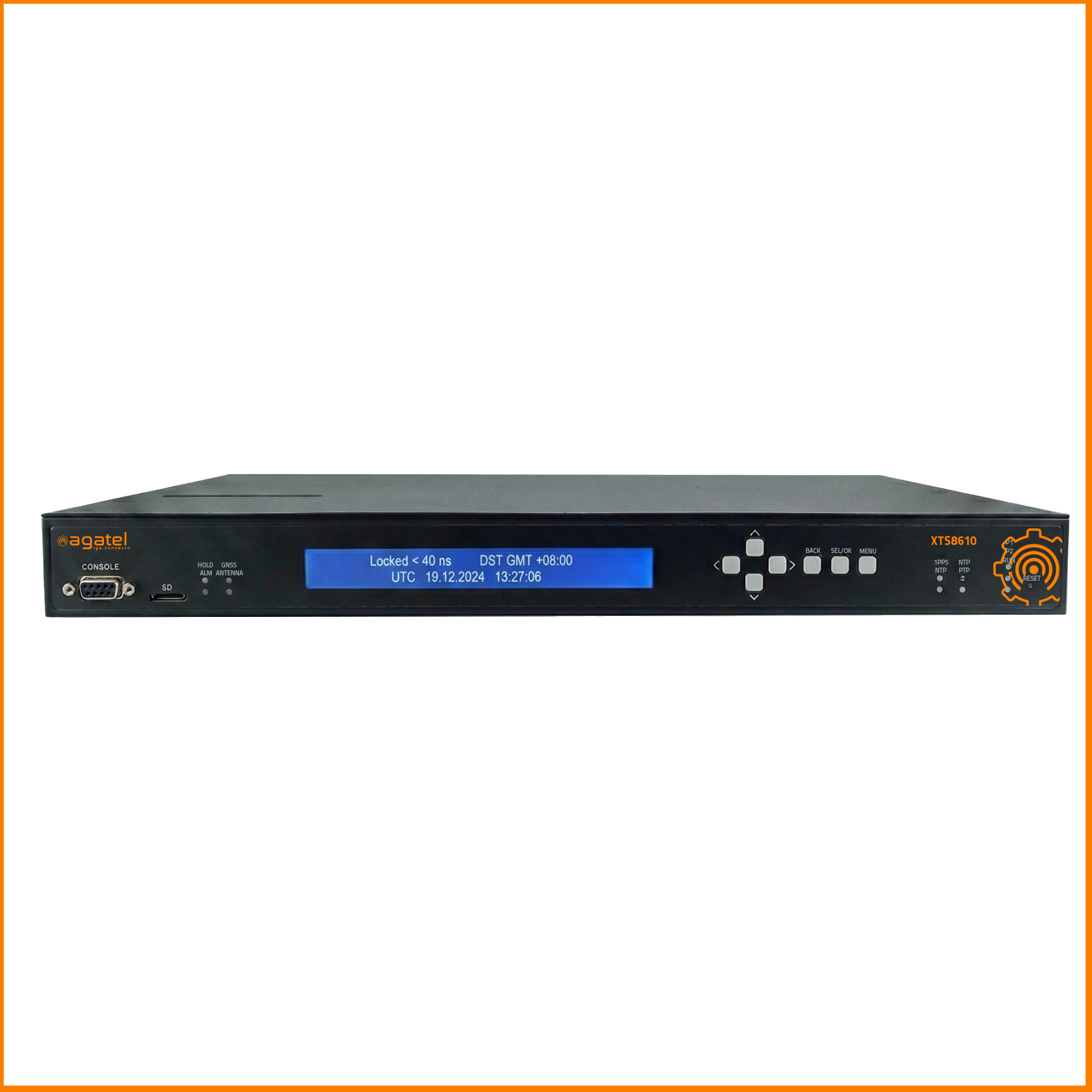
| Model Name | NTS8610 Series |
GNSS Receiver Specifications
| GNSS Input ports | 1x GNSS Input; SMA (F) – active Antenna |
| GNSS Module specific Information | Multi-Constellation Supported: GPS L1, GLONASS L1, BeiDou B1, Galileo E1 Maximum Concurrent Constellations: 3
Leap Second: Supported Sensitivity for GPS: • Tracking: -166 dBm • Reacquisition: -160 dBm • Cold Start: -148 dBm • Hot Start: -160 dBm |
| Acquisition Times | Cold Start: < 45 seconds
Warm Start: < 7 seconds |
| Antenna Requirements | 3.3 V, < 50 mA
Minimum gain=5dB; Maximum gain + Cable Attenuation ≤ 40dB |
| GNSS Vulnerability Mitigation | Jamming: Support Detection, Warning and Switch to OCXO Holdover
Spoofing: Support Detection, Warning and Switch to OCXO Holdover (GNSS Antenna Only) |
| Antenna Vulnerability Mitigation | Antenna Cable Short: Support Detection, Warning and Switch to OCXO Holdover
Antenna Disconnection: Support Detection, Warning and Switch to OCXO Holdover |
Multiple Bands GNSS Receiver Specifications
| GNSS Input ports | 1x GNSS Input; TNC (F) – active Antenna |
| GNSS Module specific Information | Multi-Constellation Supported:
GPS: L1C/A, L2C or L5 Galileo: E1, E5a or E5b BeiDou: B1I, B2I or B2a GLONASS: L1OF NavIC: L5 Maximum Concurrent Constellation: 4 Leap Second: Supported Sensitivity for GPS + GLONASS + Galieo + BeiDou • Tracking: -167 dBm • Reacquisition: -160 dBm • Cold Start: -148 dBm • Hot Start: -157 dBm |
| Acquisition Times | Cold Start: < 24 seconds
Warm Start: < 2 seconds |
| Antenna Requirements | 3.3 V, < 50 mA
Minimum gain=6dB; Maximum gain + Cable Attenuation ≤ 30dB |
| GNSS Vulnerability Mitigation | Jamming: Support Detection, Warning and Switch to OCXO Holdover
Spoofing: Support Detection, Warning and Switch to OCXO Holdover (GNSS Antenna Only) |
| Antenna Vulnerability Mitigation | Antenna Cable Short: Support Detection, Warning and Switch to OCXO Holdover
Antenna Disconnection: Support Detection, Warning and Switch to OCXO Holdover |
Antenna Specifications (Accessories)
| GNSS Antenna | GNSS receiver: GPS L1, GLONASS L1, BeiDou B1, Galileo E1 LNA Gain: 40dB min
Weather-Proof Housing: IP69K Operating and Storage Temperature: -40°C ~85°C ESD: ±15KV Air Discharge Mechanical size: 66.5 mm dia. x 21 mm H MIL-STD-810F Supply Voltage Range: 2.5 to 16VDC |
| GPS Antenna | GNSS receiver: GPS L1, Galileo
Weather-Proof Housing: IP69K Operating and Storage Temperature: -40°C ~85°C ESD: ±15KV Air Discharge Mechanical size: 66.5 mm dia. x 21 mm H MIL-STD-810F Supply Voltage Range: 2.5 to 16VDC |
| Anti Jamming GNSS Antenna | GNSS receiver: GPS L1, GLONASS L1, BeiDou B1, Galileo E1 LNA Gain: 40dB Typ.
Weather-Proof Housing: IP69K Operating and Storage Temperature: -40°C ~85°C ESD: ±15KV Air Discharge Mechanical size: 66.5 mm dia. x 21 mm H MIL-STD-810F Supply Voltage Range: 2.5 to 16VDC |
| Multi-Bands GNSS Antenna (XTS8610) | GNSS Receiver:
GPS: L1C/A, L2C or L5 Galileo: E1, E5a or E5b BeiDou: B1I, B2I or B2a GLONASS: L1OF NavIC: L5 LNA Gain: 37dB min Weather-Proof Housing: IP69K Operating and Storage Temperature: -40°C – 85°C ESD: ±15KV Air Discharge Mechanical Size: 66.5 mm dia. x 21 mm H MIL-STD-810F Supply Voltage Range: 2.5 to 16VDC |
| Max. Antenna Cable Length | Antenna cable:
Without amplifier: LMR-400: 150M CFD-200: 50M RG58A/U: 25M With Amplifier: LMR-400: 250M CFD-200: 80M RG58A/U: 50M |
| Max. Sync-out Cable Length | RG58 A/U Sync-Out cable:
1PPS, 10MHz, IRIG-B TTL: 150M IRIG-B AM: 150M @1K impedance, 300M @10K impedance IRIG-B RS485: 1200M |
Proven Clock Accuracy (Relative to UTC)
| 1PPS | ±40 ns Peak *1 |
| Demodulated IRIG-B | ±40 ns Peak *1 |
| Modulated IRIG-B AM | ±1 μs Peak *1 |
| RS-485 IRIG-B | ±100 ns Peak *1 |
| PTP Timestamp | ±40 ns Peak *1 |
| NTP Timestamp | ±50 us Peak , ±40 us Average *1 |
| Holdover accuracy – OCXO | < 0.5 us / 8 hours / < 72 us / 7 days *2 |
| *1. Device locked to satellites for at least 24 hours.
*2. Device locked to satellites for at least 48 hours before holdover |
Network Interface
| Ethernet Standards | IEEE 802.3 10BaseT
IEEE 802.3u 100BaseT(X) IEEE 802.3ab for 1000BaseT(X) IEEE 802.3u for 100Base-FX IEEE 802.3z for 1000Base-X |
| Gigabit Ethernet Ports | Two Combo ports, 2x 10/100/1000BASE-T(X) RJ45 or 2x 100/1000 Base-X SFP Support Synchronous Ethernet (SyncE) per ITU-T G.8261 ITU-T, G.8262 and G.8264 ESMC), PTP-Capable and NTP-Capable |
| Fast Ethernet Ports | 2x 10/100 BASE-T(X) RJ45, NTP-Capable |
LCD Display and Control Buttons
| LCD Spec | Character Display LCD 40×2
5×8 Dots Includes Cursor LCD Operating Temperature Range: -20°C to 70°C LCD Over-Temperature Protection |
| Control Buttons | Up, Down, Left, Right, Menu, Enter, Back |
I/O
| Console | 1x DB9 Serial Console Port |
| SD Slot | 1x micro-SD slot |
| Relay-Alarm Contact | Three Pins Relay with NC, NO and GND.
Rated Operational Voltage: 24-250 VDC Continuous carrier: 3 A max. 75VA max Dropout Time: ≤ 6 ms typical Pickup time: ≤ 8 ms |
Sync Module S2
| Sync1 ~ Sync2 | Two configurable output channels (coaxial BNC (F) connector):
1. 1PPS/PPM/PPH Output (Square Wave, configurable pulse width) 2. IRIG-B TTL Output (Support IEEE 1344 and C37.118.1) 3. AFNOR French Time Code Output 4. ASCII Timestamp Output* |
| Sync3 ~ Sync5 | Three configurable output channels (Sync 3 – Sync 5, coaxial BNC (F) connector):
1. 1PPS/PPM/PPH Output (Square Wave, configurable pulse width 2. IRIG-B TTL B000~B007 Output (Support IEEE 1344 and C37.118.1) 3. IRIG-B AM B120~B127 Output (Support IEEE 1344 and C37.118.1) 4. AFNOR French Time Code 5. ASCII Timestamp Output* |
| Sync6 | One configurable output channel (Sync 6, TB3 connector):
1. IRIG-B RS-485 B000~B007 Output (Support IEEE 1344 and C37.118.1) 2. AFNOR French Time Code Output |
Sync Module S3
| Sync1 ~ Sync2 | Two configurable output channels (coaxial BNC (F) connector):
1. 1PPS/PPM/PPH Output (Square Wave, configurable pulse width) 2. IRIG-B TTL Output (Support IEEE 1344 and C37.118.1) 3. AFNOR French Time Code Output 4. ASCII Timestamp Output* |
| Sync3 | One configurable output channel (Sync 3, coaxial BNC (F) connector):
1. 1PPS/PPM/PPH Output (Square Wave, configurable pulse width) 2. IRIG-B TTL B000~B007 Output (Support IEEE 1344 and C37.118.1) 3. IRIG-B AM B120~B127 Output (Support IEEE 1344 and C37.118.1) 4. AFNOR French Time Code 5. ASCII Timestamp Output* |
| Sync4 | One configurable input channel (coaxial BNC (F) connector):
1. IRIG-B TTL B000~B007 Input (Support IEEE 1344 and C37.118.1) 2. 1PPS input 3. AFNOR French Time Code TTL Input |
| Sync5 | One configurable modulated input channel (coaxial BNC (F) connector):
1. IRIG-B AM B120~B127 Input (Support IEEE 1344 and C37.118.1) 2. Modulated AFNOR French Time Code Input |
| Sync6 | One configurable input/output channel (Sync 6, TB3 connector):
1. IRIG-B RS-485 B000~B007 Input (Support IEEE 1344 and C37.118.1) 2. IRIG-B RS-485 B000~B007 Output (Support IEEE 1344 and C37.118.1) 3. AFNOR French Time Code RS-485 Input 4. AFNOR French Time Code RS-485 Output |
| Sync7 | One configurable output channel (ST (F) connector):
1. 1PPS/PPM/PPH Output (Square Wave, configurable pulse width) 2. IRIG-B TTL Output (Support IEEE 1344 and C37.118.1) 3. AFNOR French Time Code Output 4. ASCII Timestamp Output* |
Electrical output Drive Levels
| 1PPS/IRIG-B TTL Output | 5VDC 125 mA TTL compliant |
| Modulated IRIG-B Output | 5Vp-p, 3.3:1 ratio, AM, Sinewave |
| 1PPS/IRIG-B TTL Input | 5VDC HCMOS, > 2.0V High <0.8V Low |
| Modulated IRIG-B Input | 1Vp-p to 8 Vp-p, ratio 3.3:1, AM |
| IRIG-B Fiber TTL | 820nm, Different fiber size: 50/125um, 62.5/125um, Output Driver Typ. 13.1uW |
| IRIG-B RS485 Input/Output | ±5 VDC IRIG-B Half-Duplex; 32 Transceivers Max. a bus |
Frequency
| Oscillator | Advanced managed OCXO, with temperature drifting compensation |
IEEE1588 Profiles
| Default | IEEE 1588V2 (PTPv2)
Default UDP (IEEE1588-2008 Annex D and J) Default 802.3 (IEEE1588-2008 Annex F and J) |
| Power | IEC/IEEE61850-9-3-2016 Power Utility Profile
IEEE C37.238-2011 Power Profile, with VLAN support IEEE C37.238-2017 Power Profile, with VLAN support |
| Telecom | ITUT-G.8265.1 Frequency
ITUT-G.8275.1 Phase/Time ITUT-G.8275.2 Phase/Time |
| AVBTSN | 802.1AS Profile |
| Enterprise | Enterprise profile |
| *Media Broadcast
(In Development Plan) |
SMPTE ST 2059-2
AES67 Media Profile |
System Moods
| GNSS Locked Mood | Synchronizes time with GNSS signals for high accuracy |
| Handover Mood | Maintains time using the OCXO clock after GNSS is unavailable |
| Free Run Mood | Operates independently using RTC as the time source along with the OCXO clock |
Functions
| Network Synchronization | RFC 1119 (NTPv2) Server
RFC 1305 (NTPv3) Server RFC 5905 (NTPv4) Server RFC 1769 (SNTPv3) Server RFC 2030 (SNTPv4) Server |
| Network Protocols | VLAN (IEEE 802.1q) filtering/tagging
IEEE 802.1p QoS DSCP IPv4, IPv6 TCP, UDP DHCP Client TACAS+/ RADIUS |
| Redundancy | Devices Clustering (NTP Only)
PRP (IEC 62439-3) Bonding – Active & Backup Bonding — LACP Combo Ports |
| Management | HTTP, HTTPS
SNMP v1/v2,v3 SSH/ Telnet (CLI), could be enabled/disabled Console CLI Estimated Time Accuracy GNSS Status Power Status PTP & NTP Status SD/MMC Backup & Restore |
| Events & Alarms | Event
Log Syslog Relay & Alarm Management SNMP Trap |
Physical Characteristics
| Housing
Dimension (W x H x D) Weight Installation |
SPCC w/Zinc Plated Body + Aluminum cover IP40 Metal Housing
440 x 300 x 44 Chassis made of 1 mm SECC Sheet
3.9KG Max 1U Rack-mountable |
Power Supply Modules
| DC Module | Rated Supply Voltage: ±24 – ±60 VDC
Input Voltage Range: ±20 – ±66 VDC |
| AC Module | Rated Supply Voltage:
110 – 240 VAC, 50/60 HZ 110 – 250 VDC Input Voltage Range: 85 – 264 VAC, 50/60 HZ 88 – 300 VDC |
| Power Consumption | Approximately 15 W (Typical)
Approximately 20 W (Max) |
Environmental Limits
| Operating Temperature
Storage Temperature Operating Altitude Ambient Relative Humidity |
-40°C to +85°C (-40°F to 185°F)
-40°C to +85°C (-40°F to 185°F) 5100m 5% to 95% (Non-condensing) |
Regularity Approvals
| Safety | LVD EN 62368-1 (Certified Operating Temperature: 75°C), IEC 60255-5 | ||||
|
EMC |
FCC(EMI): FCC Part 15, Subpart B, Class A CE(EMI): EN 55032, EN 61000-6-4, Class A
EN 61000-3-2 (Current Harmonics) EN 61000-3-3 (Voltage Flicker) CE(EMS): EN 55035, EN 61000-6-2 CE(GNSS): EN 303 413. EN 301 489-19 IEC 60255-25, IEC 60255-22-1 |
||||
|
|
|||||
|
|
|||||
|
|
|||||
| Power Automation | IEC61850-3, IEEE 1613 | ||||
| Test | Item | Value | Level | ||
| IEC 61000-4-2 | ESD | Contact Discharge Air Discharge | ±8KV
±15KV |
4
4 |
|
| IEC 61000-4-3 | RS | Enclosure Port | 10(V/m), 80-3000MHz
20(V/m), 80-1000MHz |
3 | |
|
IEC 61000-4-4 |
EFT |
AC Power Port DC Power Port Signal Port | ±4.0KV
±4.0KV ±2.0KV |
4
4 Special |
|
|
IEC 61000-4-5 |
Surge |
AC Power Port AC Power Port DC Power Port DC Power Port Signal Port |
Line-to Line±2.0kV Line-to Earth±4.0kV Line-to Line±1.0kV Line-to Earth±2.0kV Line-to Earth±4.0kV |
4
4 4 3 4 |
|
| IEC 61000-4-6 | CS | 0.15-80MHz | 10V rms 0.15-80MHz, 80% AM | 3 | |
| IEC 61000-4-8 | PFMF | (Enclosure) | 100A/m continuous, 1000A/m (3s) | 5 | |
|
IEC 61000-4-11 |
DIP |
AC Power Port |
30% reduction (Voltage Dips), 1 period
60% reduction (Voltage Dips), 50 period 100%, reduction (Voltage interruptions), 5 period 100% reduction (Voltage interruptions), 50 period |
– |
|
|
IEC 61000-4-16 |
Main Frequency Voltage | DC Input Port Signal Port | 30V Continuous, 300V 1s 30V Continuous, 300V 1s | 4
4 |
|
| IEC 61000-4-17 | Ripple | DC Input Port | 10% of unit | 3 | |
|
IEC 61000-4-18 |
Damped Oscillatory |
AC Power Port |
2.5KV common,
1KV differential mode @ 1MHz |
3 |
|
| Signal Port Telecommunication Port | 2.5KV common,
1KV differential mode @ 1MHz |
3 |
|||
|
IEC 61000-4-29 |
DC Voltage Dips & Interruptions |
DC Input Port |
30% Reduction (Voltage Dips):0.1 sec 60% Reduction (Voltage Dips):0.1 sec 100% Reduction
(Voltage Interruption):0.05 sec |
||
| IEC 60255-22-1 | 1 MHz burst
immunity |
AC Power Port
AC Power Port DC Power Port DC Power Port Signal Port |
Line-to Line±1.0 kV
Line-to Earth±2.5 kV Line-to Line±1.0 kV Line-to Earth±2.5 kV Line-to Earth±1.0 kV |
||
| Shock Drop Vibration | MIL-STD-810G Method 516.5
MIL-STD-810F Method 516.5 MIL-STD-810F Method 514.5 C-1 & C-2 |
||||
| RoHS2 | Yes | ||||
| MTBF | 20 years | ||||
| Warranty | 5 years / Upgradable to 10 years | ||||
| Physical Characteristics | |
HousingDimension (W x H x D) WeightInstalleation Power inputs |
SPCC IP30 Metal Housing
223 x 251 x44 mm (not including screws and rack-mount kit) TBD 1U Rack-mountable 24-60 VDC(Dual Input) or 110-240VAC/12–240VDC |
| Environmental Limits | |
| Operating Temperature Storage Temperature Ambient Relative Humidity | -40°C to +70°C (-40°F to 185°F) / LCM display maximum 0 to +70 °C
-40°C to +75°C (-40°F to 185°F) / LCM display maximum -30 to +80 °C 5% to 95% (Non-condensing) |
| REGULATORY APPROVALS | |
| Regulatory Approvals | |
| Safety | EN/IEC 62368 |
|
EMC |
FCC Part 15, Subpart B, Class A, EN 55032, EN 61000-6-4:Class A, EN 61000-3-2, EN 61000-3-3 |
| Power Automation | IEC61850-3, IEEE 1613 |
| Test | Item | Value | Level | ||
| IEC 61000-4-2 | ESD | Contact Discharge Air Discharge | Contact Discharge Air Discharge | 4
4 |
|
| IEC 61000-4-3 | RS | Enclosure Port | Enclosure Port | 3 | |
| IEC 61000-4-4 | EFT | AC Power Port DC Power Port Signal Port | AC Power Port DC Power Port Signal Port | 4
4 4 |
|
| IEC 61000-4-5 | Surge | AC Power Port AC Power Port DC Power Port DC Power Port Signal Port | AC Power Port AC Power Port DC Power Port DC Power Port Signal Port | 4
4 4 3 4 |
|
| IEC 61000-4-6 | CS | 0.15-80MHz | 0.15-80MHz | 3 | |
| IEC 61000-4-8 | PFMF | (Enclosure) | (Enclosure) | 5 | |
| IEC 61000-4-11 | DIP |
AC Power Port |
AC Power Port |
– |
|
| IEC 61000-4-12 | Damped Oscillatory | AC Power Port | AC Power Port | 3 | |
| Shock Drop Vibration | MIL-STD-810G Method 516.5
MIL-STD-810F Method 516.5 MIL-STD-810F Method 514.5 C-1 & C-2 |
||||
| RoHS2 | Yes | ||||
| MTBF | TBD | ||||
| Warranty | 5 years | ||||
| Model | Technology | Ethernet | G.Ethernet/SFP | GNSS Module | Sync Module | Power Modules |
| XTS8610 | GPS | 2 | 2 | Single Band | N/A | Support Two Hot Swappable
Power Modules. 2x NTS8610-AC or 2x NTS8610-DC or 1x NTS8610-DC + 1x NTS8610-AC |
| XTS8610M | GPS | 2 | 2 | Multi-Bands | N/A | |
| XTS8610-S2 | GPS | 2 | 2 | Single Band | S2 | |
| XTS8610M-S2 | GPS | 2 | 2 | Multi-Bands | S2 | |
| XTS8610-S3 | GPS | 2 | 2 | Single Band | S3 | |
| XTS8610M-S3 | GPS | 2 | 2 |
Multi-Bands |
S3 |
| Power Modules | |
| XTS8610-DC | Rated Supply Voltage: ±24 – ±60 VDC
Input Voltage Range: ±20 – ±66 VDC |
| XTS8610-AC | Rated Supply Voltage:
110 – 240 VAC, 50/60 Hz 110 – 250 VDC Input Voltage Range: 85 – 264 VAC, 50/60 Hz 88 – 300 VDC |